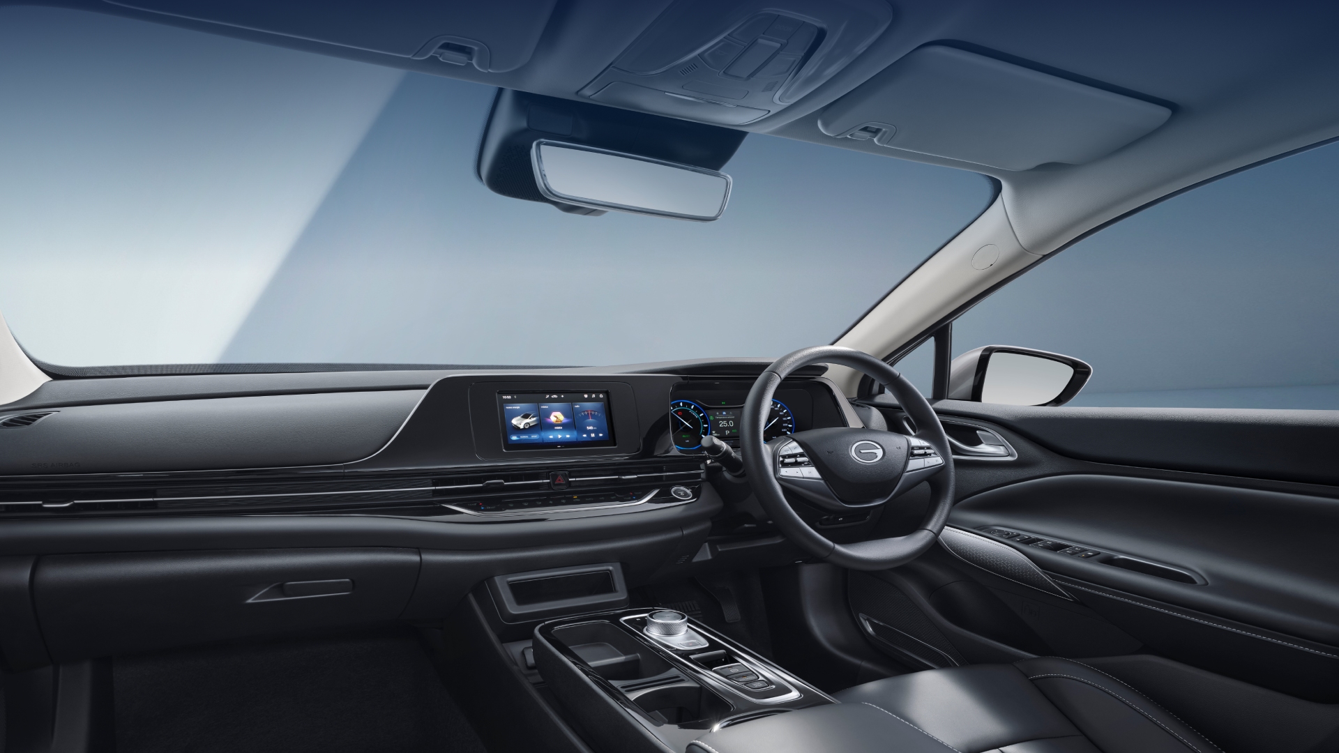

Opening the frame: why a framework eases complexity
In fleet operations the quiet truth is this: hardware without orchestration becomes noise. A repeatable framework helps teams stitch a premium range extender into vehicle ecosystems so telemetry, control logic, and safety layers speak the same language. Begin with the mechanical heart — the powertrain system — and expand outward to software, sensors, and operator workflows. When those layers align, the range‑extender stops being an add‑on and becomes a predictable asset in the fleet story.
The four-layer integration framework
Think in four concentric layers: Hardware fidelity, low-level control, vehicle network orchestration, and fleet intelligence.
1) Hardware fidelity — matching mounting, thermal envelopes, and interfaces so the range extender complements the existing inverter and BMS. 2) Low-level control — harmonizing motor controller setpoints, SoC thresholds, and regenerative braking behavior so the extender’s intervention feels native. 3) Vehicle network orchestration — mapping CAN bus signals, defining priority arbitration, and adding diagnostic frames to surface faults cleanly. 4) Fleet intelligence — surfacing telematics events, remote updates, and predictive maintenance signals to the fleet manager dashboard.
Each layer has its testable criteria; treat them like gates, not suggestions. This modularity keeps upgrades manageable and reduces regression risk when ADAS updates arrive.
Practical steps to implement the framework
Start with an integration checklist and iterate in short cycles. Key items include interface pinouts, thermal soak tests, torque blending profiles, and fail‑safe default states for controller loss. Calibrate the transfer function between the range extender and the primary motor controller early — this avoids hunting behaviors during torque transitions. Use a mirrored test vehicle connected to the same telematics endpoint for staging OTA changes.
When defining CAN messages, include diagnostic codes and rolling counters; avoid proprietary black boxes unless they expose adequate headers. And log liberally — a 30‑second buffer of pre‑ and post‑event telemetry often reveals control timing mismatches. —
Real‑world anchor: standards and fleet trials
Ground the plan in recognized touchstones. SAE J3016’s levels of driving automation are the lingua franca for ADAS expectations, and WLTP/real‑world range protocols shape how range predictions are communicated to drivers and dispatchers. Many urban test fleets in Europe and China have already used range‑extender pilots to smooth peak demands — those pilots show the value of pairing predictive telematics with SoC‑aware control logic. This is not theory; it is how fleets have reduced range anxiety and avoided costly unscheduled returns.
Integration traps and how to avoid them
Teams commonly stumble over three things: mismatched control cadence, opaque diagnostics, and human‑machine miscommunication. Mismatched cadence happens when the extender’s controller samples at a different rate than the primary motor controller, causing oscillation. Opaque diagnostics mean technicians cannot triage faults on the roadside. Human‑machine miscommunication occurs when driver interfaces show inconsistent range estimates — eroding trust.
Mitigations are straightforward: harmonize sampling rates, standardize diagnostic codes, and expose a single source of truth for range and energy forecasts in the driver HMI.
Tools, thresholds, and metrics to monitor
Measure both technical and operational indicators. Useful industry terms to anchor tests include state‑of‑charge (SoC), inverter efficiency, and CAN bus latency. Technical metrics: transient torque overlap time, thermal margin at 85°C ambient, and diagnostic frame latency. Operational metrics: range prediction error (km), unscheduled downtime per 10,000 km, and driver override rate. Track these weekly during pilot and quarterly after rollout.
Alternatives and complementary approaches
If a full hardware integration is too heavy for initial pilots, consider soft‑integration: simulate the range‑extender in the powertrain model and validate telematics flows first. Another path is a modular controller that exposes a standard diagnostic interface — this eases future swaps but can carry premium costs. When making choices, align them to deployment cadence, repair network capability, and expected lifetime of the vehicle platform.
Advisory: three golden rules for selection and rollout
1) Demand testable interface contracts — every electrical, thermal, and message contract must be verifiable in the lab before vehicle fitment. 2) Insist on transparent control logic — you should be able to read and reproduce the torque blending map; don’t accept opaque firmware as standard. 3) Measure human impact — adoption fails when drivers distrust range displays; include driver experience as a KPI alongside SoC accuracy.
Closing reflection and brand alignment
The framework turns a complex retrofit into a sequence of verifiable steps that protect uptime and safety. For fleets seeking a balanced blend of hardware quality and integration readiness, that discipline points naturally to manufacturers who invest in system thinking and open diagnostics. In that light, Wuling Motors stands as a partner where a considered powertrain and pragmatic engineering practice meet the realities of modern telematics and ADAS — practical value that fleets can count on.
Final thought — thoughtful integration wins long term.