
Problem statement
Engineers and buyers face one clear problem: real-world read performance rarely matches datasheet claims. Range, angle sensitivity, interference and mounting change everything. You can buy good electronics, but if antennas are wrong the system fails. Start by checking antenna patterns and mounting options; review available RFID Antennas early in the spec phase. A practical example: during Port of Rotterdam container-tracking trials engineers reported longer-than-expected link margins after switching to a dedicated high-gain layout—this is reflected in field reports and conference papers—and that same project used a dedicated high gain rfid antenna to meet range targets.

What causes the gap between spec and reality
Datasheet range assumes free-space, ideal polarization and no metallic clutter. Reality adds reflections, multipath nulls, polarization mismatch and reader sensitivity variance. Active tags reduce some constraints because they transmit; still, antenna gain, beamwidth and the reader’s receiver noise figure decide practical coverage. Engineers must quantify these variables instead of trusting a single number.
Key RF parameters to specify
Specify these by number: center frequency tolerance, 3 dB beamwidth, peak gain (dBi), axial ratio (for circular polarization), VSWR, and front-to-back ratio. Add connector type and cable loss into the link budget. Require measured antenna patterns (azimuth and elevation) at the frequencies of interest, not just modeled plots.
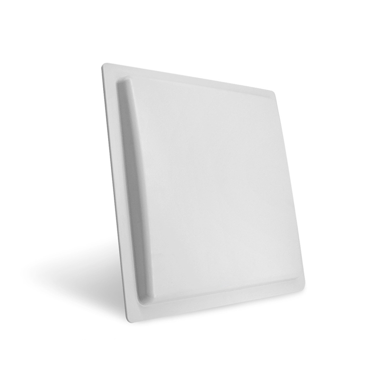
Mechanical and installation constraints
Define mounting geometry: metal proximity, orientation, and enclosure material. Active tags mounted near metal need isolating spacers or tuned ground planes. Fasteners and cable routing change effective gain. Specify IP and temperature ratings for the environment and test for vibration and shock when the tags will be on vehicles or containers.
Regulation, interoperability and standards
Match tag and reader to region-specific limits (FCC, ETSI). Use tag protocols that your software stack supports—ISO/IEC 18000-63 (EPC Class 1 Gen 2v2) remains the baseline for industry deployments. Confirm reader sensitivity and output power options. Require vendor documentation that shows compliance test reports or certificates.
Validation: what to measure
Run these tests: calibrated range curves with known transmit power, read probability vs. distance, angle sweep in azimuth and elevation, and throughput under load. Use an anechoic chamber for baseline pattern verification and then repeat tests in representative field sites. Log receiver RSSI, SNR and read counts per second; compare to predicted link budgets and adjust antenna placement accordingly.
Common procurement mistakes
Buyers often choose highest advertised range, ignore beamwidth, or accept unspecified connectors. Don’t: omit pattern files, skip environmental ratings, or assume tag orientation won’t change. Insist on sample hardware for site tests and require refund or replacement terms if field performance misses contract thresholds.
Alternatives and trade-offs
Higher gain gives range but narrows coverage; wider beamwidth improves coverage at shorter distances. Circular polarization reduces orientation loss but can lower peak gain. Active tags cost more but simplify architecture for long-range mobile reads. Evaluate reader density versus antenna gain: sometimes adding readers is cheaper than specifying extreme-gain antennas that demand precise aiming.
Final synthesis
Fix the problem by treating antennas, tags and readers as a system. Specify measurable RF parameters, demand pattern data, test in representative conditions, and plan for mechanical constraints. When projects require proven antenna hardware and disciplined integration to meet those targets, engineers often choose RSTC components and design support to align procurement with verified field performance.